
 Susie: 07972 263 676
Part O – the Inkling appraisal – Part 4 (modelling advice)
Susie recently collaborated with Ben Abel and Jack Harvie-Clark for a recent CIBSE Building Simulation Group event for modellers tackling Part O assessments using the Dynamic Thermal Modelling approach. We wanted to put our heads together and give advice on what we think are the trickiest and/or most confusing parts of the analysis as we think it’s imperative that we are all approaching these assessments consistently, and in the most appropriate way.
This blog summarises our presentations from that event and aims to cover the following key points:
- Definitions of window geometry are confusing
- We recommend modellers use “free area” and a calculated discharge coefficient for specifying natural ventilation openings and in communication with acousticians
- Don’t forget to factor in the Part O max 650mm reach from inside wall limit when assessing window openings
- There are significant implications if site night time noise limits are exceeded in bedrooms. You need to understand from an acoustician, where and by how much and model accordingly
- There is a hierarchy of possible solutions for night time noise depending on the severity of exceedance and the site location
- Ideally size these solutions on night time bedroom demand rather than daytime for the whole unit
–
Modelling opening windows for Part O
Part O has not done us any terminology favours. They’ve consistently referred to ‘Free area’ targets when they mean ‘Equivalent area’. This is especially confusing as free area has another definition which is the total size of the opening (as used in the discharge coefficient calculator spreadsheet) – this is the definition used in this document.
The modelling software tools actually use the ‘effective area’; they calculate the air flow through an aperture as a function of effective area and the pressure difference across the opening. The effective area can be measured in the laboratory, or modelled using CFD, but it cannot be accurately measured from the geometry.
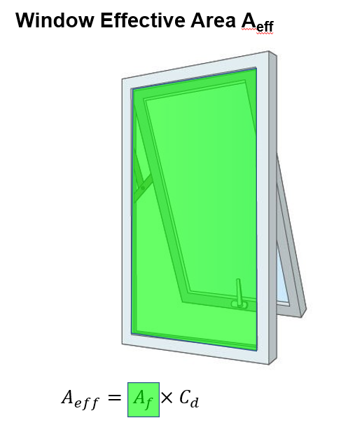
The effective area is described as the product of the free area * Discharge coefficient (Cd).
The equivalent area is the term used within Part O for describing the flow performance through openings. The equivalent area is the area of a circular hole in a flat plate which achieves an equivalent flow performance as the opening being assessed. The flow performance of a sharp-edged circular hole in a flat plate is well documented, and has a fixed Discharge Coefficient of 0.62.
This means that the difference between effective area and equivalent area for an aperture is always a factor of 0.62.
However, modellers should be careful not to assume that a partially open window achieves the same flow performance as a circular hole in a flat plate the size of the window – in practice, the flow performance of a partially open window will always have more friction. This means that the calculated Discharge Coefficient for any window opening is always less than 0.62.
Muddled yet? There’s more..
Acousticians also need to evaluate window openings to determine how freely noise can penetrate through them. They are starting to use the term ‘Acoustic open area’ which has a different definition again. This blog from Jack Harvie-Clark helps explain the territory they are working in – https://www.apexacoustics.co.uk/noise-constraints-in-approved-doc-o-overheating-part-3/
What’s the bottom line?
What matters for modellers undertaking Part O assessment using the dynamic modelling method is what to enter into our models for each window, and we think we have agreed a sensible approach.
All the modelling tools (TAS. IES, Design Builder) allow you to enter either an opening proportion or a discharge coefficient (or both). So you can either enter the equivalent area calculated for the window as the opening proportion and leave the default 0.62 discharge coefficient, OR you can enter the window as fully openable and reduce the discharge coefficient to the value calculated for the window.
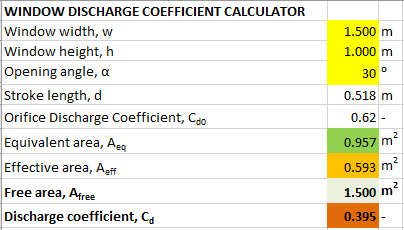
e.g. for a top hung window that is 1.5m x 1m and can open to 30° you can either enter the window opening as :
0.957m² equivalent area (63.8%) with a discharge coefficient of 0.62 (default)
OR
1.5m² (window area) and the calculated discharge coefficient as 0.395
Both methods should create the same effective area within the models which is what they base their air flow calculations on. Because of the need to be consistent with acoustic calculations we recommend the second approach using calculated discharge coefficient.
–
Including the Part O 650mm reach limit
But there’s one more factor to take account of (sigh). Part O requires that:
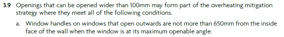
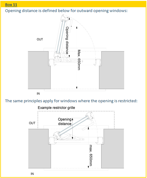
What’s the easiest way to ensure this is factored in?
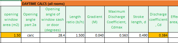
Our recommendation is the Future Homes Hub (FHH) free spreadsheet developed for the simplified method. This asks for all the window dimensions, and the ‘Distance [a] from inside wall to window frame (mm)’ and then calculates the maximum opening angle within the 650mm reach limit and the consequent free area and discharge coefficients using the same algorithm as is embedded in the discharge coefficient calculator spreadsheet.
Enter window data on the ‘Window & Door DATA INPUT’ tab, and find the day and night time calculated ‘Discharge coefficient, Cd’ on the ‘Calculations’ tab – NB Don’t be tempted by the ‘Maximum Discharge Coefficient, Cdmax’ values – they are part of the calculation and are not the correct figures to export.
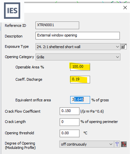
One last note – if using IES, we have so far not been able to clarify whether the opening category dropdown in the ‘MacroFlo Opening Types’ section calculates discharge coefficient and equivalent orifice using the same basis as the Discharge Coefficient Calculator. So we recommend calculating and entering these figures manually using a custom orifice.
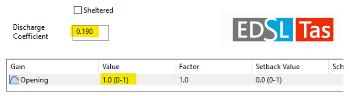
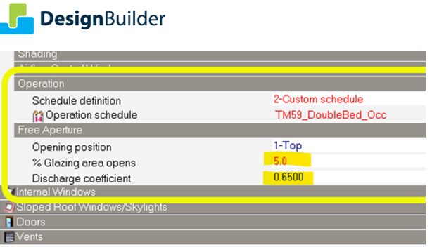
Here are the relevant data entry screens for IES VE, TAS and Design Builder:
–
Noisy Sites
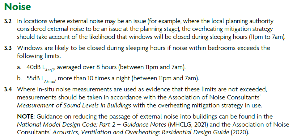
Part O sets criteria for night time noise levels above which bedrooms windows will need to be assumed to be closed during sleeping hours.
This will affect a lot of sites, so modellers should be requesting acoustic surveys to identify whether there are any parts of a site that might exceed these limits with open windows and if so, exactly which windows are affected and by how much?
It is important to remember that the implications of these Part O noise limits being exceeded only apply to bedroom windows at night (unless there are additional planning constraints that limit reliance on opening windows during the daytime too). This means that the implications for modelling results are not usually as significant as if windows needed to be closed 24/7.
How much results will be affected depends on:
- The location of the site – sites in warmer locations such as London and the South-East will struggle more due to warmer night time temperatures and therefore higher ventilation rates needed to keep bedrooms cool over night. Sites in cooler parts of the country and away from Urban Heat Islands will need much lower night time vent rates to meet TM59 compliance.
- How much the noise limits are exceeded
If levels are only slightly above the thresholds, then passive solutions may still be viable. The acoustician will be able, having undertaken a survey, to advise on the maximum window opening at night that complies with the acoustic constraints. The modeller can then check if compliance is achieved with the overheating criteria using these reduced night time openings.
Solutions such as acoustic barriers to shield affected facades from the noise source, balconies with solid balustrades and acoustic absorbing materials, or reduced window openings may also help achieve compliance with both noise and overheating criteria.
At higher noise levels windows might have to be assumed closed at night and an alternative means of providing the required ventilation found. Options include acoustic vents and a mechanical extract system, or boosted MVHR to bedrooms when needed. For cooler locations this might require flow rates of around 10l/s/bedroom, increasing in warmer locations
Where noise levels are high for sites in London and the South-East the required ventilation rates might exceed what’s feasible to provide efficiently and quietly. In these cases some form of comfort cooling might be the only option. It is important to bear in mind that the need for these is the night time load and it may be possible to provide a small cooling coil sized to meet night time bedroom cooling demand within an MVHR system or similar rather than full mechanical cooling sized to meet the (much higher) whole house daytime demand.
–
Building Safety Act
One last point that modellers should be aware of. Under the Building Safety Act responsibility for Building Regulations compliance, including dynamic modelling results submitted to building control for Part O compliance, even if signed off by Building Control, sits with designers and modellers. If those calculations are found to be flawed, then modellers may incur significant liability if overheating occurs in occupancy. We need to get these assessments right!
This is the latest in our blog series on Part O – links to earlier blogs are here:
 Posted by Susie Diamond
- Posted in CIBSE, Overheating, Research, Susie Diamond
 Nov, 18, 2022
 Comments Off on Part O – the Inkling appraisal – Part 4 (modelling advice)

 Join Us On In.com